As a manufacturer of multi-spindle lathes, we at AXIS started asking ourselves some time ago how we could support our customers in tackling this practical, daily challenge.
While a few years ago the only possible answer was the consistent precision of the mechanical cam, industrial automation today offers a winning alternative: the flexibility of the electronic cam.
Together with one of our customers, we got straight to the heart of the matter by designing a custom solution. It was a partnership that allowed both of us to reach a small yet significant milestone: on one hand, their production made a leap in quality; on the other, we developed a new capability to better serve those who choose to partner with us.
Before walking you through this project, let's start with the basics: in this first article, we will compare the operation and limits of mechanical cams versus electronic cams. This will give you the tools to understand when to prefer one over the other and when, instead, the best choice is to make them work in synergy.
In a multi-spindle lathe, the machining cycle required to produce a component corresponds to a 360° rotation of the camshafts. The synchronization of all operations planned across the 6 or 8 drum work stations is coordinated by this kinematic system, which converts the constant rotary motion of the shafts into linear movements of the tool slides—and, consequently, of the cutting tools mounted on them.
In this setup, there are two primary tool motion directions:
- Radial cams: Move the tools perpendicular to the workpiece, performing external and parting operations (such as facing and cut-off).
- Axial cams: Move the tools parallel to the workpiece axis, managing end-working and axial feed operations (such as drilling and longitudinal turning).
Since each slide is controlled by a dedicated, specific cam, every tool takes on a defined and independent linear position for every single degree or range of degrees throughout the machining cycle. Consequently, at the exact same degree of drive shaft rotation, different slides carry out independent operations—each with its own specific displacement value and feed rate. This independence allows cycle times to be optimized by perfectly tailoring the movement of each individual tool to the specific operation of its position.
Precisely because of this simultaneous action, the final cycle time required to produce the part is determined solely by the longest single machining operation among the 6 or 8 positions. The duration of all other operations, occurring in parallel, is completely absorbed by the slowest one.
It is worth noting that within this 360° rotation, the idle time (indexing time) is also included: a fraction of the cycle's degrees is used to rapidly retract the slides, index (rotate) the drum to move the spindles to the next position, and lock it in place for the start of the next cycle.
To summarize the process dynamics simply: with each drum index, the metal bar stock advances at the first position to enter the machining area and begin forming. At the final position, the completed component is cut off and discharged from the lathe. Meanwhile, across the intermediate positions, the bar diameter is progressively machined into shape.
But how does the simple rotary motion of a shaft transform into such a complex, precise, and repeatable sequence of linear geometric slide movements? Through the mechanical cam.
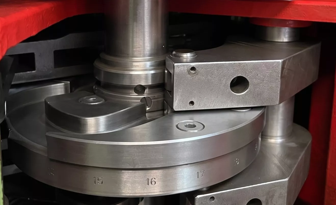
From a construction standpoint, a mechanical cam is a flat steel disc with an asymmetrical profile engineered with rise ramps, dwell sections (constant radius), and fall ramps. This component is keyed directly onto the radial and axial camshafts, which host a specific cam for each working position and rotate in perfect synchronization.
As the shaft turns, the outer profile of each fixed cam acts as a track for a lever's roller follower. The resulting thrust culminates in the linear movement of the tool slide, achieving the conversion from rotary motion into linear working motion.
The flawless kinematic synchronization of this mechanism provides intrinsic anti-collision safety: the direct mechanical coupling between the shafts and the cam profiles guarantees a constant, rigid, and unalterable coordination among the various slides.
However, despite this mechanical precision, the system's main limitation becomes apparent during job changeovers. Whenever workpiece geometry changes, the lathe must be re-tooled by partially or completely replacing the cams to adjust strokes and movements. This manual setup, carried out by a technician, results in extended machine downtime that reduces flexibility—especially when managing small lot sizes.
It is in this scenario that automation becomes an invaluable asset through the electronic cam.
Its operation relies on a synergistic relationship between two core elements managed by a PLC: the Master (guiding axis) and the Slave (driven axis).
The Master acts as the independent variable—the absolute reference point to which the entire system synchronizes. The Slave is the dependent variable whose kinematic state (position, velocity, acceleration) is calculated real-time as a function of the Master's state.
The mathematical motion law governing this relationship is:

To apply this concept to a multi-spindle lathe: the Master is a rotary axis representing the entire machine cycle (360°). The real position of the machine’s main mechanical shaft is read continuously by an encoder and converted into a digital signal. The Slave is the tool slide, driven by an independent motor that translates back and forth, faithfully following the geometric profile of the electronic cam defined in the software. By extending this principle across multiple workstations, the slides remain perfectly synchronized with one another because they all draw from the exact same digital Master.
In short: the electronic cam replaces mechanical linkage with a software link, replicating through code and absolute mathematical precision what a physical steel profile would accomplish mechanically.
This movement digitalization goes beyond theory—it redefines production efficiency while preserving traditional operational practices.
On fully mechanical machines, a setup technician can turn the machine slowly by hand using a mechanical handwheel linked to the main shaft to visually verify movements, inspect critical clearance points, and ensure tools will not collide. The major advantage of the electronic cam is its ability to seamlessly integrate into this manual workflow: when the operator uses the handwheel to turn the machine, the electronic axis detects the movement of the main shaft (acting as the Master) and responds accordingly. Adhering strictly to its programmed motion law, this Slave slide advances or retracts in perfect lockstep with the mechanical components—exactly as if driven by a physical steel profile. The result is total component coordination that eliminates collision risks at the root during verification setup.
Furthermore, once a cam’s motion "recipe" is defined and validated, adjusting positions during changeovers no longer requires manual intervention. Switching to a new part simply involves selecting the appropriate recipe or recipe set directly from the operator panel (HMI). Physical cam replacement and fine-tuning are replaced by an instantaneous digital changeover. Integrating electronic cams at strategic points on the machine radically transforms production efficiency by cutting setup times—drastically reducing idle downtime and delivering the flexibility required for short production runs.
Additionally, this hybrid approach utilizing localized electronic cams offers a clear advantage over placing standard CNC slides in those same positions. In the event of a cycle stop, a conventional CNC axis loses its kinematic reference and requires a homing procedure. By contrast, an electronic cam remains continuously linked and synchronized to the mechanical camshafts: regardless of sudden stops or pauses, the Slave always knows the exact position of the Master, eliminating recovery time. You get the geometric accuracy of numerical control—powered by brushless motors and ball screws—seamlessly integrated with the native kinematics of a mechanical multi-spindle lathe.
Now that we’ve covered the fundamentals, our next article will dive into the core of the project: we’ll share our first application of a specialized electronic cam designed for secondary machining operations.
At this link, you can find a short video preview demonstrating how the movements of the two electronic cams are analyzed slowly using the handwheel:
https://youtube.com/shorts/jVkGSquIUXE
Stay tuned!